Press brake tools descriptions and recommendations.
How to choose correct press brake tools for your needs

Hello there! Before making this article I tried to study carefully what information is already available and I found that all the published recommendations mainly are marketing articles or other words from Wikipedia what is air bending, coining, and acute punch. So or I looked not all, or there are not a lot of things useful. Because we think that the best customer - the customer who knows what he wants, will be glad to give them some of our knowledge, info, and experience.
Please note: copying even partially is possible only after permission and with credit to our website/company. Any information could be used without prior notification with the proper credit to us for non-commercial purposes. We have the right to claim in any way if we will find our sources used without any permission and approval.
Some ways of bending could be "experimental" so try only at your own risk. This article is informative, and we are not responsible for any results unless it was additionally and clearly confirmed by us officially.
Parts:
Introduction
Our customers and their requests
Necessary information for the study
Press brake tools to install - suitable tooling
Types of press brake tooling
Details of bending punches
Details of bending dies
Details of tooling sets
How to choose the proper bending tooling
Introduction
Before we tried to make many articles about various details about press brake tools/tooling. But now we suppose that it is better to make one and detailed article about all. It is not promotional text and we believe that it can help operators and engineers with bending planning and can concentrate the main details from a lot of main sources and books. This article is highly recommended to read for operators and engineers with any level of skills but for sure for beginners for sheet metal bending.
For engineering and R&D departments this information could be quite useful to get the main principles for the development of geometry of new parts or preparing the technological instructions for the production.
For direction and owners of small factories and workshops, this information could be useful to understand and plan the bending tooling management, improvements in this field, and main purchases as the way to get the most economic and effective choice for your production.
We would like to make a warning and notes that mainly we believe that our experience and knowledge are much lower than the experience of a qualified operator of press brake who is active with main daily bending operations in constant activity. Moreover, we recommend that for any calculations, verification, and checks you should verify the information with your CNC control which is adapted to your model of the press brake as the most precise way to get the main information, strokes, tonnages, and bending sequences.
Please note - here you will find nothing about coining.
Coining is the press brake bending method where the complete pressing of punch into the metal and die. It could help to reduce the radius of bending, repeat exactly the form, remove the spring back to zero, and request a lot of tonnages. During our experience, we never received the request for bending of standard bends with the coining so we will ignore this type of bending for any explanation.
So everywhere we are talking about air bending - which means the bending with 3 contact points (tip of punch and shoulders of the die) but not touching the bottom of the die groove. This is the classical method of bending to use optimized tonnage but has the possible spring back of material after bending.

Pic - air bending schematics
Our customers and their requests
To tell the truth, mainly all our potential customers have different categories of requests like:
This introduction of specification of customers doesn’t have useful technical information but is important to make the conclusions of the above which are following for all the requests.
Necessary information for the study
A lot of customers make requests without providing information about your machine/press brake. This is highly important information so for your first request you should inform about:
 Manufacturer and model of the machine - it can help to understand stroke, daylight, and other important information Tonnage available
The bending force of the machine or available tonnage means the declared tonnage for the machine in technical data. Moreover, it is also important to know do you have the declared tonnage distributed for full length only or if you can use it all for the small length.
For example, you have the machine 220 tons / 3 meters. In the classic method, you have 220/3 = 73,33 tons per meter. The question is - can you use 220 tons (or for example 160 tons) for 1 meter only to bend something small but thick? This information is mainly should be provided by the manufacturer of the press brake.
Bending force for bending means max. obtained force for the bend. Bending force is calculated according to the thickness of the part, material, opening of the die, and other bend requirements. This parameter could be calculated by CNC control of the machine, various charts, and calculators.
LengthBending length - declared bending length of the press brake as the length of the table and the max. possible length for the tooling installation. Bending length usually shows the possibility of length being bent with the press brake. Bending length could be standard (usually declared) or inside the columns (which is the same as the distance between the columns) for the parts which require deep positioning inside the throat.
DaylightDaylight or opening means the max. possible distance from the top position of the beam and the bottom table without the installed tooling. For systems with non-removable and non-replaceable clamping systems like WILA, it is correct to indicate daylight between holders with the indication of information of them. Daylight information is non-important for small parts but if you want to bend big and deep parts and boxes or deep profiles it is important to verify that the maximum allowable daylight is bigger than necessary for the part with installed tools. A lot of manufacturers sell bigger daylight models with increased distance specially for big and deep parts to bend.
Clamping system (if non-typical or standard to provide detailed information about it).Sometimes even the width of the main beam is needed for the complete study of the project.
For any drawings to make the level of importance.Tooling manufacturers should understand that if it is hard or impossible to make bending of several parts with one set, what bends and parts are the most important to produce and what should be studied first.
What bending and press brake tools are already on your machine?Probably some of them could be used in new projects, mainly dies. Moreover, we had requests where changing if bending sequences removed the collisions and in fact, the customer finally didn’t need any other tooling and can work with the tools they already had.
What do you want?If the customer already made some studies based on catalogs, codes, or products of other manufacturers.
All information about the parts to bend.It could be a drawing or sketch with all the main information - thickness, material, geometry, and all bends. If there are additional requirements (for example no scratches allowed on the part) they should be specified as well because this could require special bending film or nylon or polyurethane tooling offer. The purpose of the part could be also helpful just to understand the type of industry.
Press brake tools to install - suitable tooling
First, it is correct to speak about the installation of press brake tools. Before choosing the correct tooling to use it is necessary to verify that the tooling could be installed on your machine. So it is reasonable to tell about 2 levels of choice:
Suitable tooling - any press brake tools which could be installed on your press brake without additional adapters, devices, or clamps. Proper tooling - the correct tooling to bend your part.
Tooling system or clamping system - construction of holders for upper and lower tools (punches and dies) for press brake machine defined by the manufacturer to perform the safe, correct, and parallel fixation of the tools to perform the correct transfer of force, centering of bending start and crowning of the press brake if presented. Tooling systems could be manual or mechanical (with the use of mechanical units or screws), pneumatic (with the use of compressed air) or hydraulic (use of the additional hydraulic system), also CNC-controlled.
If we will speak about suitable tooling it is important to say that there are a lot of various tooling systems with different clamping types depending on your press brake model, manufacturer, and holders on your machine. Main systems which are used in the world:
Promecam / Euro / European - the most common system for a lot of different manufacturers as well as for European brands and mainly for 95% of Asian production machines Trumpf-WILA - the system which is used mainly for Trumpf press brakes and any press brakes equipped with WILA holders Bystronic-Beyeler - the systems of Beyeler and Bystronic press brakes LVD - the systems for LVD press brakesMeanwhile to know just the system is not enough! For old press brakes for example available old Beyeler S, more modern Beyeler R, and today used Beyeler RFA. The same for LVD - there are several old systems and present LVD-W. There are a lot of different modifications of Promecam systems - for example, even Amada has different clampings for European or USA/Japanese markets. And there are a lot of old systems that we are considering today for us as specials like Haco, Weinbrenner, EHT, OMAG, Colgar, Komatsu, Durmazlar, etc.
When we are looking at the identification of the press brake system we need to speak about 3 main questions:
Punch tang means the special part of the punch which will be clamped by the clamp blocks/plates to be attached to the beam of the press brake. The geometry of tang if the groove presented provides anti-fall and reduction of risk for misplacement, both sides with the same geometry provide the possibility for mirror positioning (for example for Trumpf / Wila / Bystronic, etc.), moreover in a lot of systems the main force is provided by the top of the tang.

Pic - Example of tang - Promecam system
Die clamping tang or geometry is the part of the die to be installed on the press brake table. Die could be installed mainly on the table or special die support if presented. In some systems, for example, Trumpf / Wila / Bystronic / Amada inserts die has not to have a flat bottom but additional tang on geometry to be clamped in support.
Mainly information about the centerline is not very important for present systems - it is well-known and the chance of get a mistake is very low. Centerline - the theoretical line which should be considered as the center of bend and in this way - the center of punch tip to contact the metal. But for old systems and even if the force is not passed through the top of the punch tang the identification of the correct positioning is very important. The punch tip is completely based on centerline positioning and the most possible tonnage from the beam is passed at the centerline. The displacement of the punch tip off the centerline means the reduction of the possible tonnage of the machine and the punch itself.

Pic - Position of centerline - Promecam system
So to finalize - to understand what tooling is suitable you should know your system and main dimensions, in other words - what tools you can install on your press brake. Next, you can take the suitable catalog of tooling to choose what to purchase or what to request from the manufacturer.
Interesting to note that there could be also various solutions. There are no companies that make standard products today the tools for the old systems or special tooling could be very expensive for production and it is more reasonable to purchase additional adapters to move to the Promecam clamping system for example.
Types of press brake tooling
Now we need to move to the “proper tooling” which means choosing the tool from the catalog which will be good to bend your part or what mainly should be ordered for your production. And to speak about it we need to make a complete brief of tooling types and possibilities. We will try not to base on any tooling system but just the possible geometry of tools and their possibilities for bending.
If you have the beginner level it is reasonable also to make a small introduction to press brake tooling itself and to divide it into the simple following categories:
Bending punch - an upper tool so the tool will be attached directly to the moveable beam of the press brake or upper holder on the beam and will be moved together with the beam. We select punch based on the necessary tonnage, angle of bending, and the main geometry to perform the bend.
Bending die - a lower tool to be attached to the press brake table or lower support and stay fixed. During the bending, the punch goes into the die. We select the die first of all based on the material thickness and angle of bending. Die is also the way to reduce the necessary tonnage to bend - a bigger die than recommended means a requirement for a bigger flange for the part, and a bigger radius of bending but lower tonnage during the bending.
In other words, if you will use V16 die for a 2 mm thickness of mild steel or a V32 die for a 2 mm thickness of mild steel for a V32 die you will have much lower tonnage required for bending.
Tooling sets - complete sets of tools including upper and lower parts (mainly part and die) but used for special applications so a lot of times cannot be used without each other (like Z-bending tools) or used with a lot of limitations (like hemming punch). So these tools are usually sold, manufactured, supplied, and used only as a complete set together.
Adapters, holders, clamps, intermediate, fixation devices, etc. - everything to be installed between the parts and construction of press brake and punches and dies.
Punches and dies could be also solid or made as the main holder and insert (for example radius tools).
Today there are also a lot of special solutions to use press brakes as the machine to perform force and to install also punching units for example (to make holes, notching, louvers, etc).
Very rare (we know about some special projects) tools could be reversible and the punch will be installed at the bottom and the die on the top. The main reason is the expansion of the possible flange part which will hit the bottom table during the use of standard bending tools. It is very uncommon but we are showing the real ideas and you can know that it could be possible as well.
Pic - Inverted tools: punch on the bottom, die on the top. With this interesting construction is used the height of the intermediate is to make a return bend without any problem with the big flange
All bending press brake tools are made of metal (usually C45 or 42CrMo4, for more details you can read about our production) and hardening of working areas which are subject to stress and wear. Press brake tools are used also for different applications, for example, bar bending or profile intersectional bending. For any non-standard application, the manufacturer should know together with the request to offer the correct tooling.
All supports and holders are usually also metal but without additional hardening, because they are not stressed constantly during work. Tools made with precision can install one line without a gap which can affect and make a step on the material during the bending.
It is also important to know that no manufacturers guarantee the correct fit of tools in one line together with the tooling from another manufacturer. The reason for this is that each manufacturer has his closed production conditions and they could be different from others even if it is the same geometry of the tool.
Details of bending punches
Types of punches - punches have different geometries. Depending on the type the punches differ with the positioning of the centerline, angle, and main shape.
Punches have the following details:
General punch - main punches to use for standard bends. Could have small inclinations at the bottom part. Main radiuses 0,3-2,0 mm. 90-45 degrees as bending angle. Various geometry but the mainly straight shape with some inclination.
Straight punch - same as general punches for characteristics but simple without any inclination or grooves and mirrored both sides geometry for bending. We also include in this type the geometry which is known as “narrow punch” - a straight main part with a thin body for the possibility to bend inside to the maximum closing of flanges together. The straight punch is the old shape for the bending punch and is also widely used for all manual press brakes and bending machines and units. Theoretical centerline through the middle of the punch.
Gooseneck punch (somewhere called also “swan neck punch”) - main punches with the possibility to pass the part through the centerline, for example, bending of U-shape profiles. Have the curved geometry/opening to prevent collision with the flange of a part. Main radiuses 0,3-3,0 mm. Very universal tool for a lot of different bending jobs.
As you can see because of the special shape gooseneck punches do not have metal in the middle and they are not as strong as general, straight, or acute punches. So if you see in catalogs that gooseneck punch has a tonnage of more than 50 t/m better to check it with the manufacturer.
Acute punch - sharp punches which are used for bending of 35-26 degrees and mainly also as pre-bending for hemming / flattening applications.
Formed radius punch - usually punches bigger than R3. Could be solid or made with the inserts+holders and even for radiuses bigger than R100. The main application - to use to form the requested big radius of the part. Radiused punches could be also general, straight, or even gooseneck types. In addition, a bigger radius than the standard for punches could be used for work with thick materials because a bigger radius helps to prevent additional wear of the punch tip itself. In a lot of systems, there is the use of a universal punch holder and various radius inserts for changes.
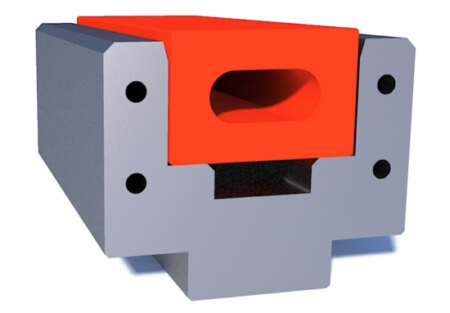
Rotax punch - Rotax is special tooling but could be various shapes with the same concept. The main construction is that up of the tool, there is an open area so you can bend closed pieces like closed boxes. The main advantage against standard tools or any other solutions like windows on the tool is that you can “open” the Rotax tool after the bending and very easily remove the part. As we told Rotax shape could be different - in the standard, it is a simple punch for 90-degree bends but could be formed radius punch as well.
About the main shape let us speak later.
About other parameters of the punch - bending angle means what angle you can have on your part. If you want to bend the part at 85 degrees you can make it with a punch equal to or lower than 85 degrees. But if you need to have a bend for 60 degrees it is impossible with 85 degrees punch so your punch should be equal to or lower than 60.
Now few words about spring back / elastic return.
Spring back or elastic return is the physical condition of the material to try to return to its original condition after bending. In bending it means returning to the initial flat / plate condition after the ending of deformation. Spring back presents in any material and is active for any deformation. In our case, it depends on the material, thickness, flatness, conditions of metal fabrication, type of deformation, the radius of bending, angle, and even grain of the surface. There is no precise information about the spring back of your material and nobody can provide it to you. Calculations are possible but also mainly theoretical because the conditions could be different even for the same material but different batch supplies.
If this information is necessary for precise study it is reasonable that you will make some tests with samples and tools in your press brake you already have and send this information together with your request. We accept also some tests by us but for this job, we request testing samples and in addition, we need to produce the test tooling to perform the test.

Pic - Demonstration of spring back. TA - theoretical angle. RA - real angle after spring back
If you have only 90-degree bends and you are planning to make only them you can get any punch of the line. Usually, it is stated differently for different systems and based on original tools. For Amada Promecam it is 88/85 degrees, for LVD - 78, for Trumpf 86, etc.
Why you should have punch, for example, 88 degrees but not the typical 90? It is simple but very important - during the air bending every time you will have spring back (or elastic return) and this factor is presented for any material deformation. So the metal after bending will have an elastic return and after bending at 90 degrees and after spring back it could have something, for example, 91,5 degrees. And it means that to have proper 90 degrees after spring back you should perform the bend not to 90 degrees, but to 88,5 to consider 1,5 for spring back. That is why on some press brakes you can find even automatic expensive systems for online angle measurement which are necessary to make an immediate correction to the bending program to bend with the necessary precision.
The radius of the punch tip should be smaller or equal to the planned radius of the part. In some sources, we encountered that should be at least 63% of material thickness. A bigger radius is reasonable - as well told it helps to prevent additional wear. If you will use a small radius for a big thickness the tip penetrating the material could start to damage very soon but anyway, you can bend the part as well. For sure you can understand that if you will have R20, your internal radius cannot be less than the punch radius. But you should be aware that the formed final radius is based on the opening of the die as well as the spring back too. It is quite common for the thin materials after bending of R50 to get the final part around 20% bigger radius after the spring back.
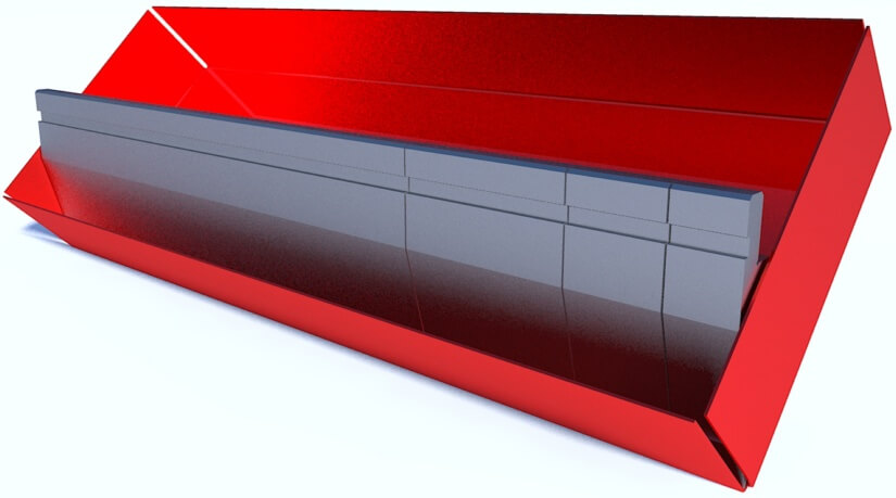
It is very necessary to give a few words about the length of the punch. There is one main rule for bending length - all bending tools should be equal to or bigger than the length of bending. Even if it will be smaller by several millimeters you can have defects on the sides. But because the bending is performed upward in a lot of applications the length of the punch should be completely equal to the bend.
Pic - bending of the flange with the sectioned punch
For example, to bend in a closed box 600 mm you should have a bending punch with a length of 600 mm, you cannot make it bigger. The same if you need to make the small partial bend with a small punch section. This is why press brake tools are also available in sections with the possibility to collect the length you need for bending. For example, you are collecting 600 mm of length as 415 + 100 + 50 + 35 mm.
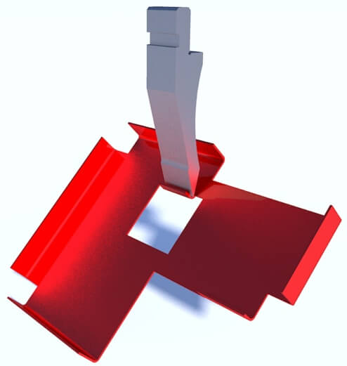
One more detail to note about horns. All main section sets are made with horns on the sides. Horns are used to prevent the collision of sided flanges during bending in the box and could be also a very effective way to bend small flanges through the punch. This is a very interesting technology and there is no even bending software today that can show and recommend to you such technology for use.

Pic - horn view during box bending and side flanges
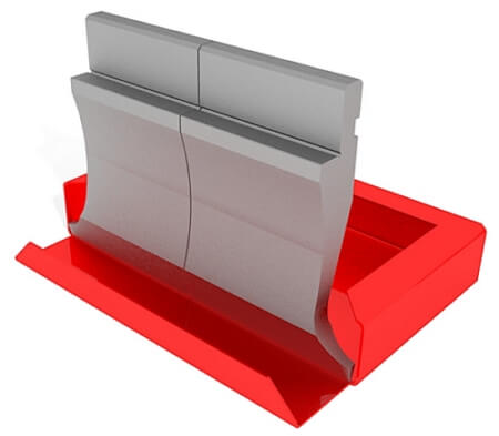
Pic - box bending with horns
Pic - example bending of closed part with horns
When you bend the closed box with side flanges with horns after the final bend you should move the part to a diagonal to extract it from the press brake. If the part has a very small width it could be very complicated or even impossible and for these purposes are used mobile horns / moveable horns (available with some general punch codes). Mobile horns are horns that could be retracted after and moved to the main punch body and thanks to this you can easily extract the bent part.
Pic - Mobile / moveable horns of bending punch
When you are choosing the punch it is very important to verify also the available tonnage. The principle is simple - more material allows to provide more tonnage for the punch itself to not destroy it during the bending. That is why for high tonnage applications the punches usually have a big width, big width of tang, and are very strong.
There are a lot of tonnage calculations so you can verify the tonnage necessary for your application. If you will exceed the tonnage allowance for the punch there is the risk to destroy or to deform it completely.
One more very small but important note that should be respected. Tools could have areas of weakness. These areas mean that even the possible declared tonnage will be not reachable and lead to punch destruction or deformation.
Usual areas of weakness:
We already spoke about the tang.
For punches, the tonnage force could be through the top of the tang or the shoulders. Each tang has the maximum allowance depending on the width, so, for example for the classic Trumpf / Wila / Bystronic system the max. possible tonnage could be 150-200 tons as well. For heavy-duty applications with thick materials which request more force, there should be completely other clamping systems, wider punches, and wider tangs so mainly exactly special press brake machines.

Pic - different geometry of Trumpf system punches with different force distribution
Many clamping systems allow mirror punch installation which means that the same punch could be installed front side or back side. For other systems like Promecam, it could be possible with a small modification of holders and adding additional clamping plates. It is very hard to imagine what part could be bent with the punch rotation (you can rotate just the part if necessary) but in some cases could be useful if you need carefully control the bending (or, for example, perform the second bending step).

Pic - mirrored punch installation
Probably all this is important to know from the beginning.
For example, we had a request to offer the tooling for a standard Bystronic press brake to bend 12 mm of Hardox with a small radius and under our calculation, the requested tonnage was around 250 t/m. And even if the press brake allows to perform such tonnage, the limitation of tonnage for the clamping system for Bystronic RFA is 160 t/m so it means that we can offer anything but the press brake of the customer doesn’t allow to perform such job and he has a risk to destroy the punch and the clamping system of the machine with the exceed of necessary tonnage. And there are no recommendations for the tools if it is impossible to reduce the necessary tonnage - the only recommendation for the customer is to change the press brake!
Details of bending dies
Different dies are used for different sheet metal thicknesses.
Dies have the following details:
It is reasonable to divide 2 types of dies as:
Centered die - the center of V-opening is positioned at the center of the die and it doesn’t request an additional adjustment for work. Non-centered die - V-openings are located not the center of the die and for the proper work it is requested that the die should be positioned by the die fixators and holders. Mainly non-centered dies are Multi-V or several V-opening dies.
The groove of the die - internal groove of the die (V-opening) as the detail of the bottom tool. In general, for a lot of cases, the V-opening is calculated as the distance between 2 intersection theoretical points of shoulders.

Pic - Die opening distance
Rule of 8 - classical rule for choosing the opening of the bending die. It means that the opening is near or equal to 8 material thicknesses. So it is 8 for 1 mm and 16 for 2 mm. It is the classical rule but it is not strict to obey. Somewhere is written to use 10 material thicknesses for thick plates more than 1/2" (12,7 mm).
Because the standard production program doesn't have precision value for all it will be used the nearest possible. For example for 3 mm - V=25 (3*8=24) or for 15 mm - V=125 (15*8=120).
What will happen with the use of a die bigger or smaller than recommended?

Pic - Variation of die opening during bending. A bigger V means a bigger radius.
The request is important as the die will be fixed. On old press brakes, there are no additional supports and holders and the die is fixed directly on the machine table. Please note that with this fixation usually there are holding plates only on the sides of the machine so to make the die parallel and to use it for the full length of bending it should be a 1 piece solid die for complete length because several separate pieces could not be clamped together without displacement.
For modern holders or die supports it is the possibility to install several pieces with a perfect fit to each other so it is possible to use even small-length dies or sectioned sets.
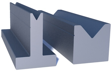
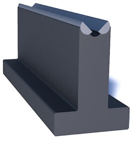
1V die - very easy, it is any die with only one opening as a classic choice for bending. Could have the outer shape of a cube or rectangle or T-form for the Promecam system. Groove is centered. If the completely flat surface is also presented it could be used for flattened / hemming applications if has a ground surface. For all big openings more than V=50-60 single V die are usually used everywhere.
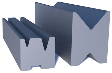
2V die - a bottom tool with 2 openings on one tool. Could be also centered not itself but with the use of special adaptors and to change the opening you just need to rotate the die itself. Moreover could be a change in the v-opening with horizontal or vertical rotation. Or could be standard non-centered which means that to change the opening you should displace the die itself on the press brake table. If the completely flat surface is also presented it could be used for flattened / hemming applications if the surface is ground.
3V/4V die - the die with 3 or 4 openings on one die on different sides. Groove is centered. If the completely flat surface is also presented it could be used for flattened / hemming applications if the surface is ground. Usually, the variety of openings allows the possibility to use the same tooling for different thicknesses depending on the part.
4V die with standard openings is a perfect solution for new presses and companies who just start the bending job. In a lot of new press brake supplies, standard general punch and 4V die are included as a starter set of tooling.
Multi-V die - die with more than 4 openings, not in the center of the tool. The purpose is the same - the possibility to use for different thicknesses but also request the allowance of the press brake die fixators to displace and adjust the die. These types of dies are quite common for old machines and Asian press brakes and usually are made for the full length of the machine, for example, 3 meters. Because of big weight such dies (or 3V/4V dies as well for big sizes) could have additional side fixation pins to rotate the die with the use of lateral chains of the press brake.
For modern presses usually, Multi-V dies are not used. Thanks to the holders there is no requirement to clamp the full length in one piece and production of these dies in Europe is very expensive. Anyway as we told you they are requested for old machines or big tonnage and big dimensions machines where changing of different dies could be a very big problem and takes a lot of time.
Variable V die - a special die that could change the opening with the mechanical, electric / servo or another way without displacement or reinstallation of the main part. The advantage of such a die is very big - you can make a change in thickness for bending without reinstallation of dies and other hard jobs with heavy pieces. Usually, such dies are used for bending thick material, just imagine that you need to change the dies V200 for example to V300 with more than 50 kg of any 500 mm and you have 6 meters machine. So you can save just a big timing of operator just to cut this job in your production facility and not any additional necessity for cranes or other loading devices.
Variable - means that the opening should be changed/adjusted. There are various ways for adjustment based on the manufacturer and his construction of offered die. It could be just a change of grooves/steps with the lifting of main units, metal plates to put in sides and to enlarge the distances, guides with manual movements and fixators (or various screws, clamps, holders, etc.), or mechanical movement.
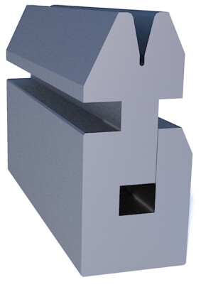
Spring die - typical dies for hemming / flattening applications. These dies have main 2 working surfaces - the first surface to make the initial bend (for example sharp bend before flattening) and the second surface - to make the final flattening. Spring dies are also used to deform the hinges as a typical special application.
For these types of dies available also pneumatic types - the spring is replaced by the air force to work for opening/closing with the supply of air pressure, even with the possibility to control from CNC if connected. Necessary to tell you that there is a strong recommendation to not use spring dies for daily standard bends - the spring wear will leave to the defect. Some manufacturers available also the type with the possibility to lock the spring for standard bends - it seems also a not good solution because in this case, the spring will stay in pressed condition. But with pneumatic control (without spring) it is possible also with closed die conditions to use it for normal bends.
Moveable roll die - the dies that have semi-spheric rollers on the top rotatable during the bend. This construction allows getting the minimal radius of bending, the minimal flange of the part, minimal deformation near the end, and reduction of friction of the material. Also, this type is necessary to use if there is a problem with the deformation of holes in the part near the area of bending.
Nylon, urethane, polyurethane dies - non-metal dies. Could be made as a complete non-metal die or as a non-metal insert with a metal holder. Nylon or rigid urethane/polyurethane dies are usually used as an alternative for standard tooling to prevent any scratching, marking, and other defects of die shoulders. Usually for this purpose could be used bending film as well with the standard tools but in some countries (for example, the USA) the industry of non-metal dies is quite big and this product is popular.
The other purpose for urethane/polyurethane dies radius bending. Elastic material allows the penetration of punch with programmed stroke and support of part from the bottom and allows the perfect bend. Based on the type of polyurethane of die it allows also possibilities impossible to achieve with standard tooling, for example bending up to 180 degrees.
In Europe bending in polyurethane has some critics - for example, the fast wear of material leads to a reduction of the repeatability of the bend in continuous production. Anyway, as we told you before it is widely used in radius bending and has lots of applications. Other advantages could be the prices to compare with classic metal tools or the possibility to use the same die and form in various radiuses of the bend.
Details of tooling sets
As we told before tooling sets are bending or forming tools that are supplied as sets and should be used only together as upper and lower parts (and additional elements if presented). Usually, you cannot use separate one part with any other tooling, or quite limited. In general, besides standard hemming sets and Z-bending tools with inserts, all other tools are special which means that they are made exactly for the application of the customer, according to his needs, request and geometry.
There are no limits for special tooling sets, they could be easy just to make special bends/forming and realized as tooling with special geometry up to very complicated, high-tech engineering solutions with additional fixators, ejectors, and guides to perform really complicated geometries with only one press brake bend.
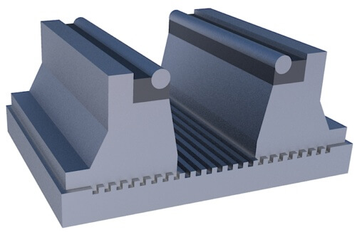
Hemming set - the most classical set of tooling with the sharp punch (acute style) and U-groove die. This set allows making bending and hemming/flattening without any tool changes. The first bend is made as a classical one to the sharp angle. With the second bend with the use of the flat surface of the punch and the flat surface of the die shoulder, the flattening is performed. The advantage of this set is that it is standard and presented usually in catalogs of all main manufacturers, it offers all operations in one set and also it could be used for standard bends (for example for 90 degrees) for other parts if necessary. So this set could be used as universal tooling for a lot of bending applications.
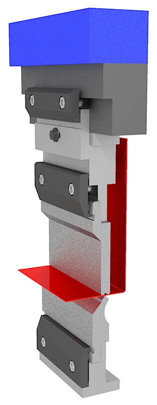
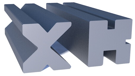
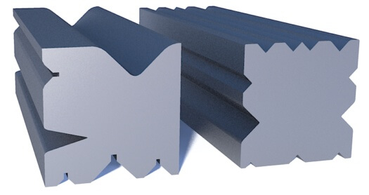
Z-bending (or step bending) set (it could be also called "joggle tools" or "offset tools") - the main application why you need a set of tooling. If the Z-distance is small you cannot use any return bend so it means that it is impossible to bend Z-form in 2 bends - you will not have the normal die for it. So to make it possible there is using of Z-bending tools to make 2 bends simultaneously.
There are several types of Z-bending tools which are:
Solid pieces mean that a special tool will be made to make the bend. Meanwhile, inserts allow you to change them with the same holders. The most interesting solution is an adjustable tool (very popular in Asia) where you can make different Z-distance with the adjustment of the main working insert with the help of small plates. So you will have Z=1 with 0 plates inside, Z=2 with 1 plate, Z=11 with 10 plates, etc. For sure it is a big advantage and a very good solution if you have various Z-bending necessities in daily production.
Even Z-bending tools could be made for air-bending or coining. The construction of tools for air-bending is preferred because allows for to reduction of the necessary tonnage when the metal will be not thin.
How to choose the proper bending tooling
Now we know the main details about the tooling and we want to understand the way how to choose the tooling for our application and part. For sure for us, it is impossible to tell everything so we can just make several important hints we use ourselves when we study the drawings from our potential customers and the ideas we can imagine that could be tried for various bending processes.
 Hint - start the study with the understanding that a press brake and tooling system could be used for the part to be bend We already told about tonnage, daylight, and everything. It is useless to study the part and possible press brake tools to use if you cannot bend it with your press brake.
Hint - use calculators. There are calculators, charts, formulas, and recommendations on what should be used for your thickness, material, the tip of the punch, etc. Check everything that is necessary for your part to proceed with the next studies. If possible to re-check from another source - better to re-check. It is quite important to know all parameters for your applications.
Hint - start the study with the understanding that a press brake and tooling system could be used for the part to be bend We already told about tonnage, daylight, and everything. It is useless to study the part and possible press brake tools to use if you cannot bend it with your press brake.
Hint - use calculators. There are calculators, charts, formulas, and recommendations on what should be used for your thickness, material, the tip of the punch, etc. Check everything that is necessary for your part to proceed with the next studies. If possible to re-check from another source - better to re-check. It is quite important to know all parameters for your applications.For critical applications check the necessary requirements together with tool manufacturers or sellers. We know that sometimes they can provide you with just the article from the catalog without verification whether will it work properly or not. Remember - better if you will check twice or triple than if you will buy the tooling that you cannot use in your production.
Hint - the last bend. The last bend is important as to how the punch will go through the part to make it. If you cannot make the last bend, all other bends are not important. So it means that we are at first checking the punch possible for the last bend and then going to complete the study of the project.
Hint - unfolding part from last to first. To prepare the bending sequence you should verify all steps. So you should collect all the bends of the part but it is better to go from more complicated geometry. For the first bends, it is much easier to find the possible solutions.
Hint - check the centerline of the bend. The rule of the centerline is very easy. If during any bend the part intercross the centerline you should choose only the gooseneck shape because the other shapes will make a collision with the part. If the centerline is not intersected and the distance to the flange of the part is more than 10-15 mm you can consider that a lot of general punches could be used for the bend.
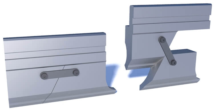
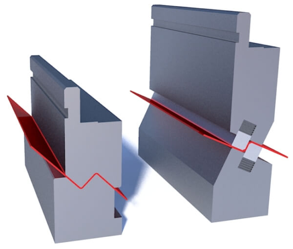
Hint - die check for any return bends. Bending is mainly up form and you should check in any bend the position of a punch. Meanwhile for bending of return bends (opposite direction of other bends) or Z-shape bending you can risk having a collision on a die when positioning the part. So for all such bends, you should check the die positioning as well. For these bends distance indicated as Z should be not less than half of the die's total width.
Pic - Check the collision of 4V and T-die during the return bends
Hint - bending sequence/bending steps are very important. You should understand that if, for example, the part has 7-8 bends, the bending sequence could be different. We had a project when the bending sequence generated by CNC control makes the collision and impossibility to proceed with the part. Simple changing of steps made everything work properly. The same could be for the tooling necessary.
Hint - inform at the beginning about your possibility to modify the dimensions of the part. Probably several millimeters increase could change the complete picture and it will be possible to offer standard tools as well. Or inform what dimensions are most important to follow without any changes. When we study the bending project we follow all the dimensions of the customer’s part. We cannot make any modifications ourselves but it is very useful to understand from the beginning if there are any modifications are possible.
Hint - during the constant bending work there is a big importance to optimize the tool change time or cut off additional operations. If you have 2 steps with different tools it is reasonable that the height of the tooling of the second “station” prevents the hit of the punch to die when you are making the first step and the same for the second step. For this, it is reasonable to get deeper dies but to exclude additional tooling installation operations.
Hint - sometimes a special tool with individual geometry for your job could be the most expensive solution but will be the best one and will work for years and return your investments very soon. Try to create together with the tooling manufacturer the best shape you need. Do not forget - standard tools could be also modified, for example with some material removal to prevent small collisions. So if you have 1-2 mm of contact you can study also the possibility to modify standard tools.
Hint - when you study a lot of parts first ignore L-shapes and U-shapes where lateral sides are much lower than bottom sides. The reason is simple - you can bend them with any tooling. The most complicated is U-profiles much deeper than the bottom and other complicated parts.
Hint - there are 2 types of parts to be bent - 2D and 3D. 2D means that you bend the profile for the full length without additional lateral bends. 3D means that you have dimensional bending and the best simple example is the closed box where you bend 2 sides and then 2 lateral sides. If you have a lot of complicated 3D parts you should think about special bending software because it is the best choice for you to develop the bends in the correct way.
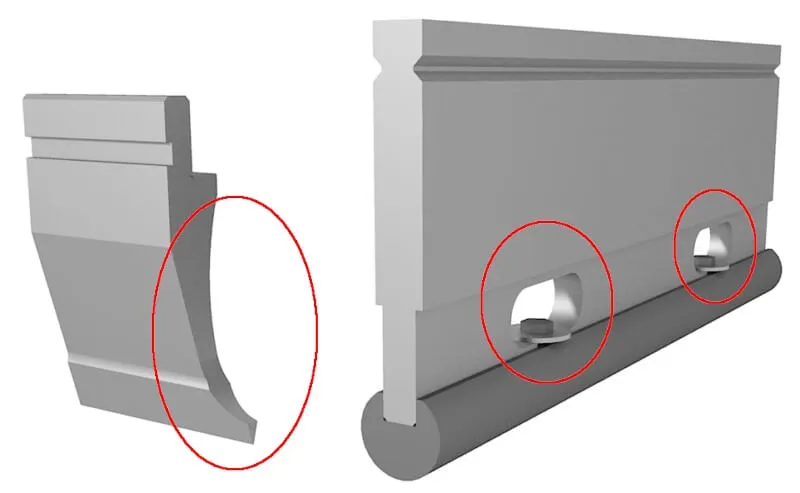
Hint - inform the tool producer about your application. For example, door profiles are mainly very complicated, and request the best special hemming table. The experience for similar parts could be quite important and you will not make fantasies about the special solution but could request the similar that already worked in other factories.
Hint - do not make the limits with only your system and catalog. You can look for standards for other bending tool systems.For example, we had a project where it was necessary for the Promecam system to use a die with a height of more than 140 mm. In the standard production line of Promecam, there are no choices, only the production of special tools. But we offered a standard Trumpf style die H=150 with a standard adapter for the bottom and this solution was the most economic, had the smallest delivery time, and was effective for use for the studied part.
Hint - normally all main visual simulations of bending as we do and could be on your CNC control show the position of the part with a 90-degree bend without note of spring back. Meanwhile, spring back compensation means that you will bend your part for an angle lower than 90 degrees to obtain the correct angle after spring back. It also means that, if, for example, you will bend for 88 degrees the position of the part (for example end of the flange) could be a little displaced. If you have a very small distance between the tool and the part you have a risk to get into a collision in reality, even if the simulation shows you that all is correct. So it is reasonable to have the tool with a little bit bigger distance to the part after bending.If we talk about spring back one more time it is reasonable to tell that normally the production should have the real coefficients based on daily bending and testing. If you want a more precise study of your project it is recommended that you will send your coefficients to the tool producer - it could make the study more realistic.
Hint - if you work with different materials first take into consideration stainless steel and hard materials with big tensile strength like special steels. For stainless steel is important to know that it will have a bigger spring back than other materials. For hard steel, it is important to know forces and tonnages to prevent the situation where you cannot bend it without risking your press brake machine.
Hint - if you bend stainless steel take a bending tooling first for it. For example, 88-degree tools are not enough for the bending of thin stainless steel to get 90 degrees bending because of spring back. Moreover, a lot of press brake tooling producers have the same prices for 88 and 85 degrees tools (first of all we are talking about bending dies) so it is better to take more sharp-angle tooling for the same price.
Hint - bending tools are heavy. Changing tools on the press brake is not the same like to change mills in machining centers. The standard section of punch can weigh 16-25 kg and if you use the tools to bend thick materials and big dies you should even need additional lifting devices to change the tools. If you plan the job with a lot of changes of tools it is reasonable to look for solutions to optimize such operations. Or you should request the smaller sections from the beginning even if you want the big length.
Hint - If you have several press brakes and different tool systems it is reasonable to look for some unification and to purchase the adapters with the possibility to use in the future any tool on any machine. It can make a fast and quick job replacement if one machine is out of service or occupied with other operations. In this way, you will also optimize the engineering job for your engineering department because in their plans they will use the same tools. For very sensitive and important parts it is recommended even to have a "spare set" so you can change tools immediately if you will have any problem with the existing set or force-majeure.
Hint - if you can change radius bending to bumping better to do it. Bumping or "Bump forming" - the way to perform the "radius bending" with the use of standard tooling. The advantages are - the use of standard factory tools and the possibility to eliminate the collisions if they could be with the standard one-radius bend. The way to make bumping is the following: bending with multiple small strokes and small angles to deform the material step by step. The positioning of the part should be performed by the automatic back gauge of the press brake to follow the bending program. You will not have a radiused shape but the main geometry will be equal as it is. One more time - bumping is the way to bend with tools you already have in your production without ordering special tools for the requested shape.In bumping, you divide the main bending angle into several smaller ones. For example, you have 90 degrees bending and you make 6 steps for 15 degrees of each (so each angle of bending is 165 degrees).

Pic - example of replacement for bumping with small bends
Hint - If you have a collision with the part there are 2 main solutions - to develop the special tool shape or modify the standard tool shape. Modification means the additional milling and removal of the material in the area of the collision. It requested additional study because the tool after a modification has reduced possible tonnage as well. Anyway, it is reasonable if the question is about 1-2 mm and the preparation of such a tool will be much cheaper and faster than the complete special tool.We meet some articles like "buy a variety of tools to have more solutions for your parts". Completely incorrect. If you have constant fixed production which means that you know more or less your parts and needs it is quite important to find or probably develop one punch for all tasks if possible than to buy 3-4 others. The reason is only one - you will save a lot of time in production for tooling changes and even if your investment will be much bigger, it will give you much more in the future. When we study several different parts from one customer the first thing we are looking for - is one punch for all. Even if the thicknesses are different.
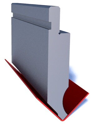
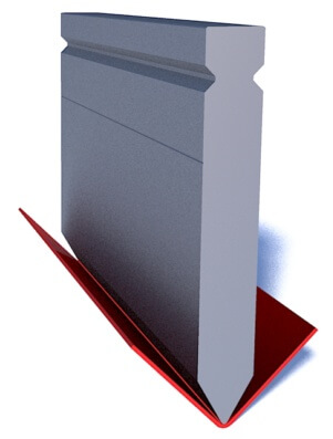
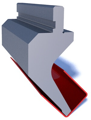
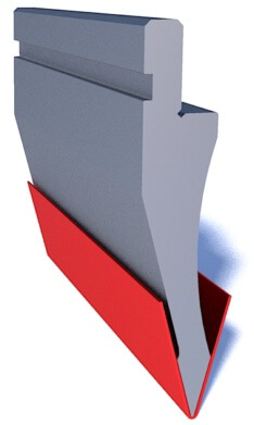
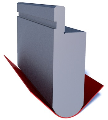
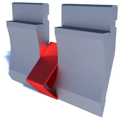
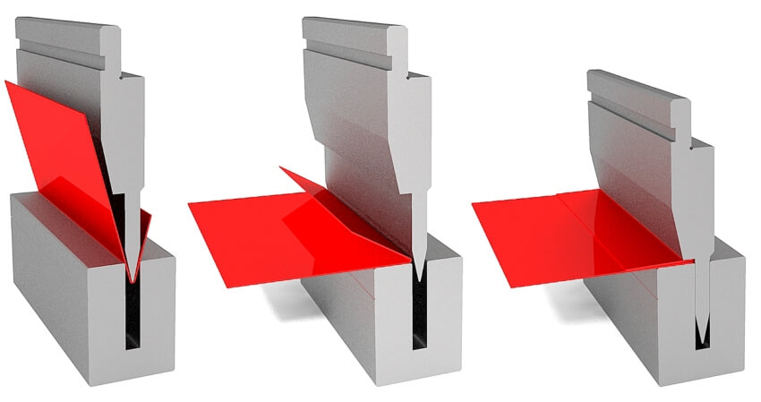
Hint - have a deep profile and no possibility to bend or are special tools too expensive? Think about reverse bending. Nobody recommends officially it to you but you can try it. If you do not request precise parts and it is allowed to bend material twice in the same place, you can realize the complex profiles bending without the use of additional and special tools. The principle of bending is to make the geometry in a way to make the final reverse bend return to a flat already bent area. It is better to explain with the picture. Because nobody can be sure about the results you can test it in the workshop and some of our customers already worked this way, meanwhile the manufacturer of the press brake or tool supplier will not recommend to you this way of bending.
Pic - simulation of bending of U-profile with reverse bending
Hint - you can do flattening also with your standard punch. But because of the risk of displacement as reverse bending nobody will officially recommend to you this technology. But for sure you can try it and eliminate the need to purchase additional tools. It could be also not the flattening but the closing of the profile after the angle pre-bend.
Hint - Tools with bigger heights are always better. They bring to you more possibilities and will be better for any deep penetration into the part if necessary. For sure tools with big height cannot negatively affect the possible opening after installation of tools - you should have enough space for your parts as well.
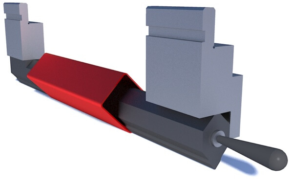
Hint - If you have a Promecam tool system it is quite effective with additional possibilities you never thought of, for example bending through intermediates. So together with the height of the punch you can get an additional 100-120 mm which could be necessary, for example, for the deep box. Moreover, special intermediates in length are also available.
Pic - bending through intermediates
Hint - For big factories with several press brakes and big storage of tooling it is necessary to implement the system of tooling management with fixation of all stored tool codes, identification of manufacturer, shape, and all general details. If you have any installed system, for example with the use of barcodes, you can request such marking during the order of new tools.
The last hint - use imagination and creativity based on possible logic of bending tools development. It is a very strange recommendation but true. There are thousands of special solutions and each of them in the past was made and designed for the first time. Everybody looks for realistic and working tools but if there is no experience they could be also developed for you. Maybe with some ideas from the previous projects. Or completely unique. Also as we mentioned before a lot of times operators know perfectly what they want to get and probably how the solution could be done. And together customer and manufacturer can prepare the effective tool for the work.
All credits D.Lotti (d.s.lotti at precitools.it), I.Protsenko (info at precitools.it) (c) 2023
 press-brake-tools.com
 live:local_218